
AMRs for Coated Parts: Keep the No-Contact Zone and Hanging Orientation in the Rack
AMRs for Coated Parts: Keep the No-Contact Zone and Hanging Orientation in the Rack
At the exit of a paint line, in a post-cure buffer, or on the route to final assembly, a newly coated part is often more sensitive than it appears. During manual moves, an operator naturally avoids a visible face, steadies a hanger, and notices when two parts are getting too close. Those small corrections cannot be assumed once the move is assigned to an AMR. A vehicle can travel smoothly while a rack still allows rubbing, witness marks, hanging swing, or a change in drainage orientation that only becomes evident at a later process step.
The useful design question is therefore not simply whether a vehicle can move a rack. It is whether the surface condition of each part remains protected through loading, travel, and handoff. An under-rack lifting AMR can provide stable support below the carrier, but the dedicated rack and its repeatable interfaces with stations should define the no-contact zone and the intended hanging orientation.
A Coated-Part Unit Is More Than a Rack That Holds Enough Parts
A general-purpose rack is often designed around capacity, access, and structural strength. A rack for coated parts must answer more specific questions. Is the load carried through an approved contact point? Is there a visible gap between front and rear faces? Can a hook, pad, or restraint touch an edge or hole without reaching a cosmetic surface? For thin panels, covers, trim parts, and formed sheet-metal components, the rack is not merely a perimeter frame. It is the device that repeatedly establishes a controlled part orientation.
Starting with the part's process datum and then designing the rack interface is normally more reliable than selecting a vehicle first and adding a few rails later. Hangers, supports, and restraints should have separate roles. A load-bearing point transfers weight to the rack. A restraint prevents swing or convergence. A protective material makes limited contact only where that contact is explicitly allowed. Temporary wrapping should not be asked to perform the job of a structural constraint. If batches differ in hole pattern, geometry, or coating condition, use exchangeable locators, model-specific zones, or clear loading rules rather than mixing them freely on one tier.
Coating quality is not determined by spray application alone. Industry guidance continues to treat contamination and surface defects as problems that need disciplined diagnosis. In the logistics segment, that is a practical reminder that contact points, residues, and orientation changes should be engineered and inspected conditions, not informal habits.
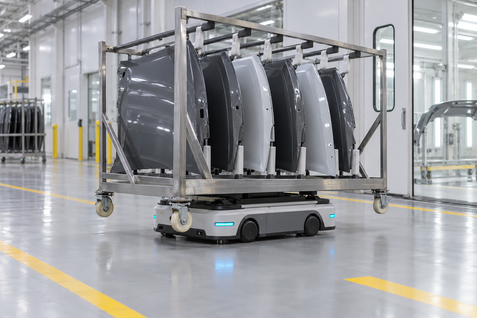
Figure 1: An under-rack AMR supports the carrier evenly while coated parts remain separated at dedicated hanging positions
Draw the No-Contact Zone and Hanging Datum Into the Rack
A no-contact zone is not just a small gap that looks adequate around a part. It must become an identifiable geometric relationship in the rack: the approved hole or datum used for hanging, the defined facing direction, the clearance to a lower rail and adjacent parts, the areas where a soft contact is acceptable, and the visible faces that must stay clear throughout the move. Where drainage, leveling, or an incompletely stabilized coating matters, the hanging direction must also follow the process requirement instead of being reversed to gain capacity.
The frame, hooks, and protective elements deserve maintenance attention as well. A worn pad can expose a hard edge. A bent hook can slowly bring two parts together. Powder, oil, or packaging debris can turn an apparently light contact into a source of a visible defect. Rather than discovering that condition only during final appearance inspection, teams can make the hanging point, clearance, and protective material part of a fast visual check before the rack is released to the AMR.
This does not require a complex sensor system for every component. Fixed, high-volume part families can use colors, silhouettes, and locator notches to distinguish hanging positions. Mixed-model racks can pair exchangeable interfaces with a loading confirmation. The important question is whether the team can determine, before departure, that every part has already entered the protective geometry of the rack.
AMR Motion Limits Should Follow the Rack's Dynamic Margin
Once an under-rack lifting AMR has entered the carrier, its lifting points should be close to the intended load center and the rack should rise evenly at structurally approved locations. The vehicle should not stop under only one side, and a caster or lower rail should not continue to carry an unexplained share of the load. During travel, it is more useful to observe whether the rack stays level and whether hanging parts approach the edge of their no-contact zone than to consider maximum travel speed by itself.
Route and motion settings also need to reflect dynamic margin inside the rack. Starts, stops, turns, floor joints, and a return to normal travel after an avoidance maneuver can all create swing. For a long hanging part, a high-appearance surface, or a tight clearance, a project team can use representative fully loaded racks on the usual route and with the least favorable part mix. The review should ask whether visible surfaces remain separated, hanging points show abnormal rubbing, the rack twists, or protective pads stay in their intended positions.
That does not mean applying one overly conservative speed to every task. A more useful approach associates the rack type, hanging arrangement, route condition, and process state with suitable acceleration, braking, turning, and route-use rules. When a rack has a temporary extra load, a missing protective element, or an incorrect loading orientation, it should be corrected in a controlled area instead of entering the main travel path with an unresolved condition.
Independent Station Support Completes the Surface-Protection Chain
Arrival at a buffer, inspection point, or assembly station is not automatically the moment to push the rack or remove a part. A steadier sequence is for the rack to settle in a fixed parking frame or location zone, for its casters or supports to take independent load, and for the AMR to lower and exit before inspection, picking, or the next transfer begins. That prevents an unexpected change in rack attitude during vehicle withdrawal and removes the need for people to pull on a part or readjust a hanger while the vehicle still carries the load.
The fixed receiving position should protect the no-contact zone too. Its guides, stops, and available space should not squeeze the rack or force access from a restricted side. A short buffer should preserve clearance between adjacent rack envelopes. For a rework part, a hold part, or a part with suspected rubbing, retaining its original rack position and hanger identity gives quality personnel a more useful basis for determining whether the condition existed before loading, during transport, or after station handoff.
With this logic, an AMR does more than replace manual rack pushing. It moves a rack under defined support, orientation, and route conditions, while the rack keeps the part surface within explainable boundaries. What reaches the next process is not merely an arrived component, but a component still in a protected state.
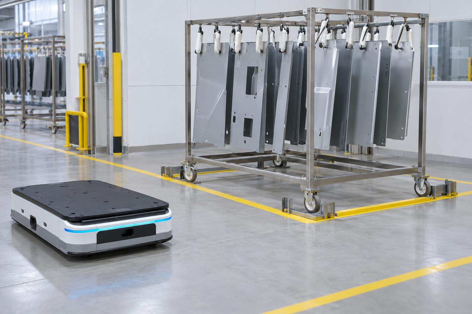
Figure 2: The rack is independently supported in a fixed parking frame before the AMR exits the support area
For coated-part logistics, the rack is not an accessory. It is the interface that carries process requirements into material movement. Define the no-contact zone, hanging datum, and allowed contact points first; then verify that under-rack lifting, route motion, and the fixed receiving position preserve those limits. That sequence keeps surface risk from being discovered only at final inspection or assembly.


邮箱
邮箱验证*
*


